The underground system «HVZ» is a huge underground «air conditioner»
Foreword and brief description of the system
Large cities are not only growing upwards and outwards; urban development also involves the use of underground space. Most city dwellers, walking through the streets of their cities, have no idea what is happening several meters (and sometimes tens of meters) below their feet (and I am not talking about the subway). Beneath the city, there are numerous communication collectors, storm drains, pipe and cable communications, technical and utility structures, communication cables, etc.
In this article, I want to show my readers an underground facility that combines several functions at once (some technologically related, some complementary). These structures are integrated into a single system and are a fairly clear example of facilities that can be located under a city. I will not disclose the location (it is not important for describing such structures), and those who know where it is should not talk about it for security reasons, because this system is partly connected with critical infrastructure facilities.
I had known about the existence of this complex of underground structures for several years and had been looking for an opportunity to go down into it. But my descent here happened by accident (unplanned). While walking with my son, I was supposed to meet a friend and colleague in urban research, Andrey Woland. I told them about the existence of this system and suggested considering the possibility of its accessibility in the future. But it turned out that one of the potential entrances was open at that moment (perhaps because part of the system is sometimes used as an underground shelter). We did not want to miss such an opportunity and immediately plunged into the object of our research.
The main function of this system is an underground cooling and ventilation center. In essence, it is a huge air conditioner that served a group of buildings. This cooling and ventilation center was built in the 1990s and is currently not in operation, as it is inefficient compared to modern ventilation and air conditioning systems. Therefore, it is now a huge system that has been “forgotten” because no new meaning (change in functional purpose) has been given to it.
This technology worked on the principle of a cooling tower (a cooling tower in which water circulates and is discharged through a stream of air). A large city fountain was installed on the surface, which in fact served as a cooling pond (the principle of water circulation is similar to cooling towers, but instead of a directed air flow, a large area of water is used here), and the air conditioning system itself, with all its pipes and air ducts, is located underground. For those who didn’t know, almost all city fountains (except decorative ones) located near large public buildings are not a matter of beauty and city improvement, but a matter of engineering support for specific structures, namely their air conditioning systems.
The structure of the “HVZ” system includes:
stair blocks;
heat exchange chambers;
boiler room;
pipe-cable manifold;
plumbing tunnel;
pump station workshop;
control room with utility block;
ventilation chamber;
public restroom.
It should be noted that all of the above-mentioned premises, except for stairwells (some of which open onto the surface on one floor), are completely underground. For the sake of logical description of the system under study, I will adhere to the described structure, supplementing it with photographs and videos.
Stair blocks, heat exchange chambers, boiler room
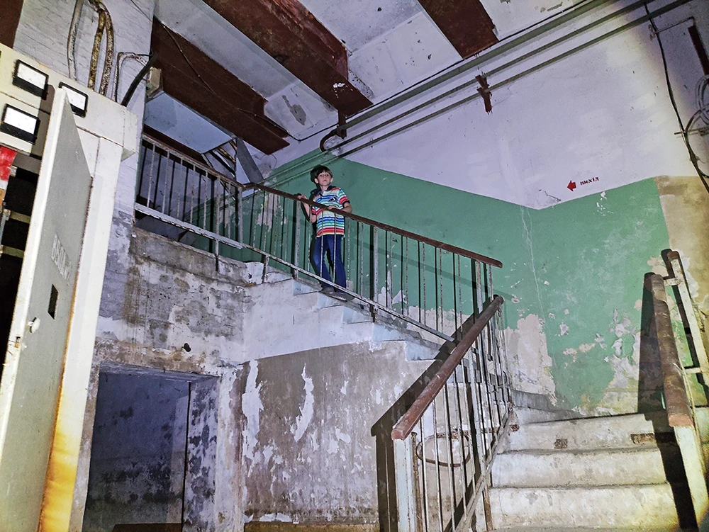
While examining this system, I counted at least six staircase blocks scattered across different areas. Due to the fact that the location of the object is actually active terrain, and different parts of the system are created at different levels, the stair blocks lead to different depths from the surface—some only one floor down, and some four floors down from the surface. There is nothing else of note to say about the vertical connections.
We entered the facility through one such external entrance. Surprisingly, the lighting was still working. Descending three floors down, we found ourselves in vestibules leading to two heat exchange chambers. Here, next to the staircase, there were small storage rooms, through which pipes once led from the outside, but now they are used to store junk.
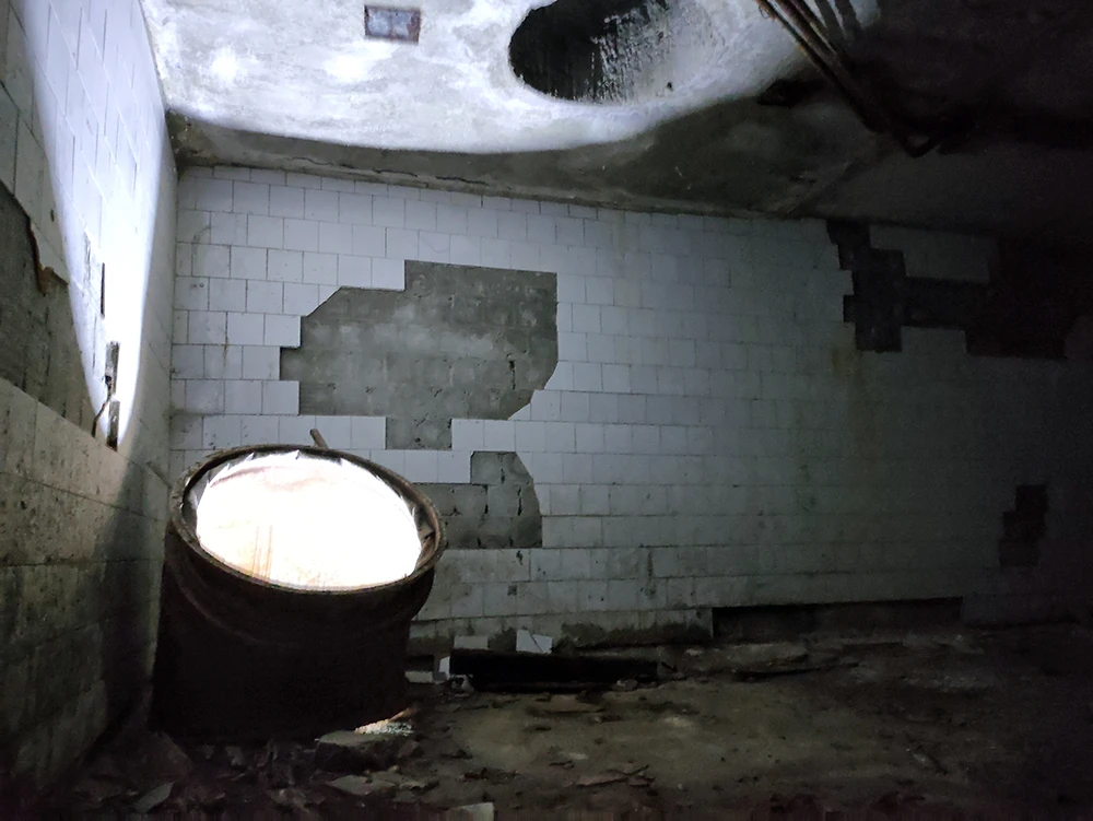
The heat exchange chamber equipment was dismantled long ago, and these rooms are now used as underground shelters under martial law. They consist of two huge halls measuring 3 meters wide, 4 meters high, and approximately 25 meters long (photos 2-3). One of the chambers borders a technical room, and when we opened the door, we smelled a foul odor. Shining a flashlight inside, we saw that the room was covered with black mold (which is quite dangerous for humans). Therefore, we limited ourselves to photographing the huge boiler without entering the room and closed the door (photo 4).
2. Heat exchange chamber. It is unknown whether there was any equipment here, but now it serves as a shelter
3. Heat exchange chamber. The only piece of equipment left here is the air duct
4. The boiler room is equipped with a huge water heating tank with a capacity of approximately 2-3 tons of water
5. Boxes are intended for civil defense
6. In the middle of one of the boxes are stored gas mask bags and RP-4 filters for them
7. Another box contained gas mask kits with smaller filters
While examining this system, I counted at least six stair blocks scattered across different areas. Due to the fact that the site where the object is located has an active relief, and different parts of the system are created at different levels, the stair blocks lead to different depths from the surface—some only one floor down, and some four floors down from the surface. There is nothing else special to say about the vertical connections.
We entered the facility through one such external entrance. Surprisingly, the lighting was working. After descending three floors, we found ourselves in vestibules leading to two heat exchange chambers. Here, next to the staircase, there were small storage rooms, through which pipes once led to the outside, but now they are used to store junk.
The heat exchange chamber equipment was dismantled long ago, and these rooms are now used as underground shelters in the current state of martial law. They are huge halls measuring 3 meters wide, 4 meters high, and approximately 25 meters long (photos 2-3). One of the chambers borders a technical room, and when we opened the door, we were met with a foul odor. Shining a flashlight inside, we saw that the room was covered in black mold (which is quite dangerous for humans). Therefore, we limited ourselves to photographing the huge boiler without entering the room and closed the door (photo 4).
Pipe and cable manifold and sanitary tunnel
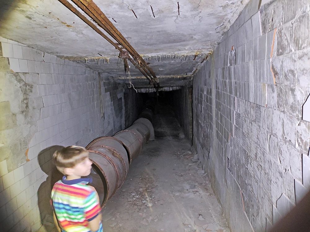
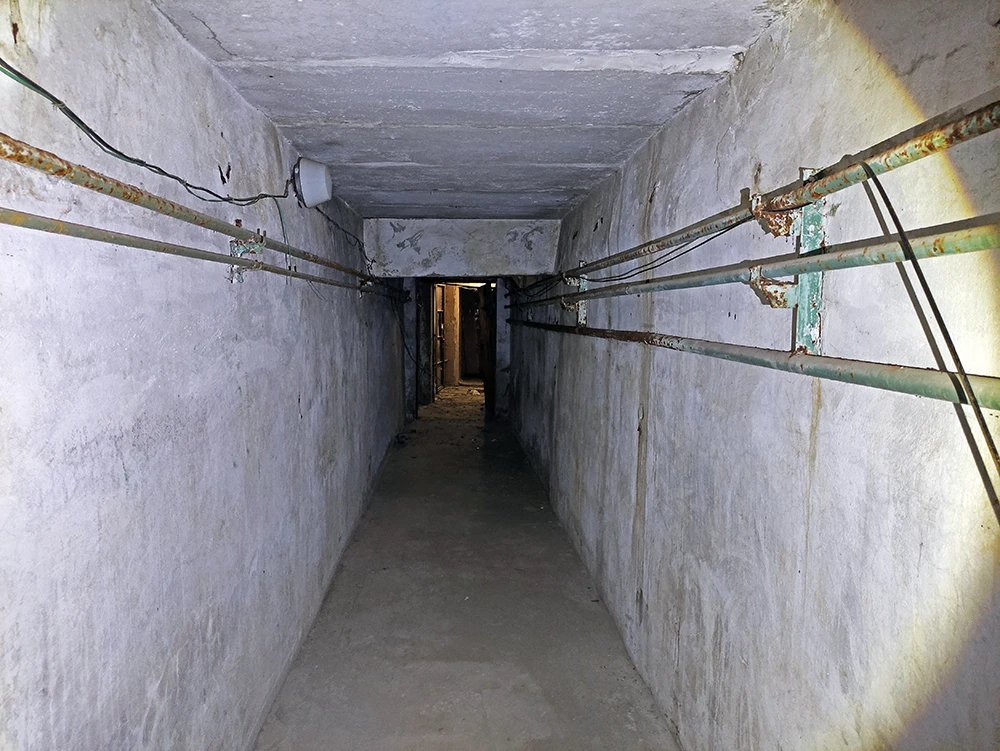
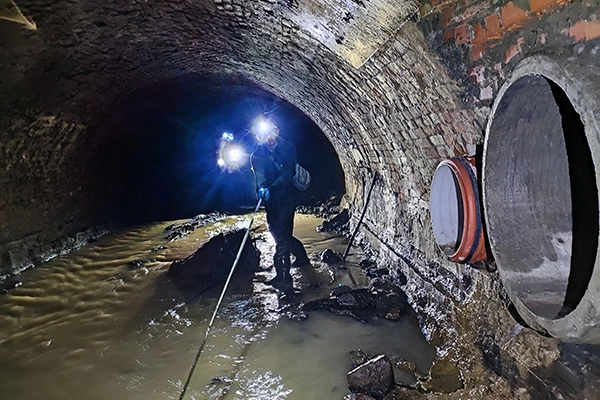
We were very interested in the lattice doors behind the gas mask boxes (photo 8). After overcoming the barrier of boxes, we found ourselves in two parallel tunnels. The one on the left was a plumbing tunnel (photo 9 – tunnel No. 1) finished with tiles, and the remains of an air duct lay on the floor. The one on the right (tunnel No. 2) turned out to be a pipe and cable collector. The tunnels started from the same room, but at that moment we did not understand whether they would continue parallel, so we went along the pipe and cable collector (pipe and cable collector) because it seemed more interesting to us.
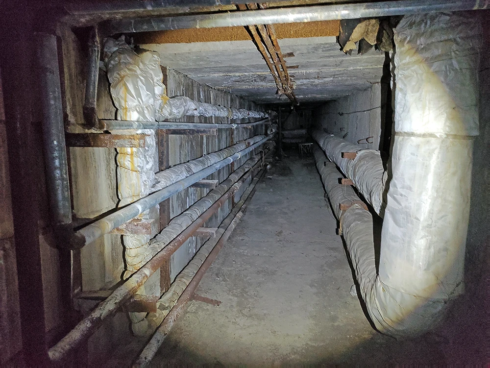
This is the first TCC I have encountered that did not have chaotically placed networks; all pipes were separated into separate groups according to their function (photo 10). The heating main is on the right, the water pipe is on the left, and there were no cables yet—they will be installed later.
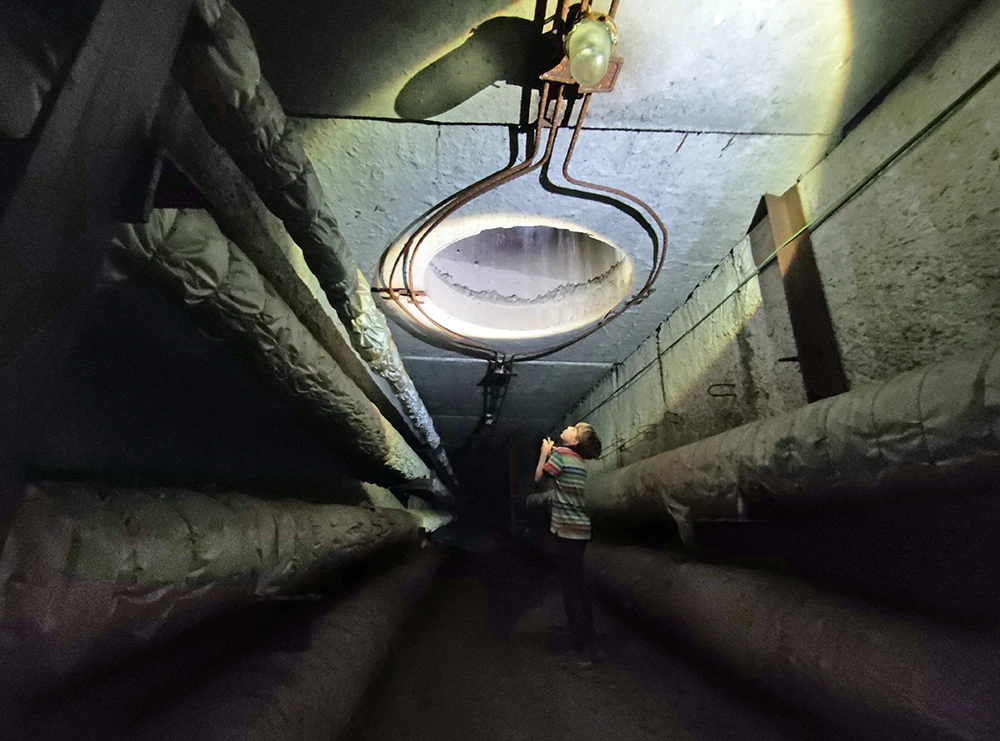
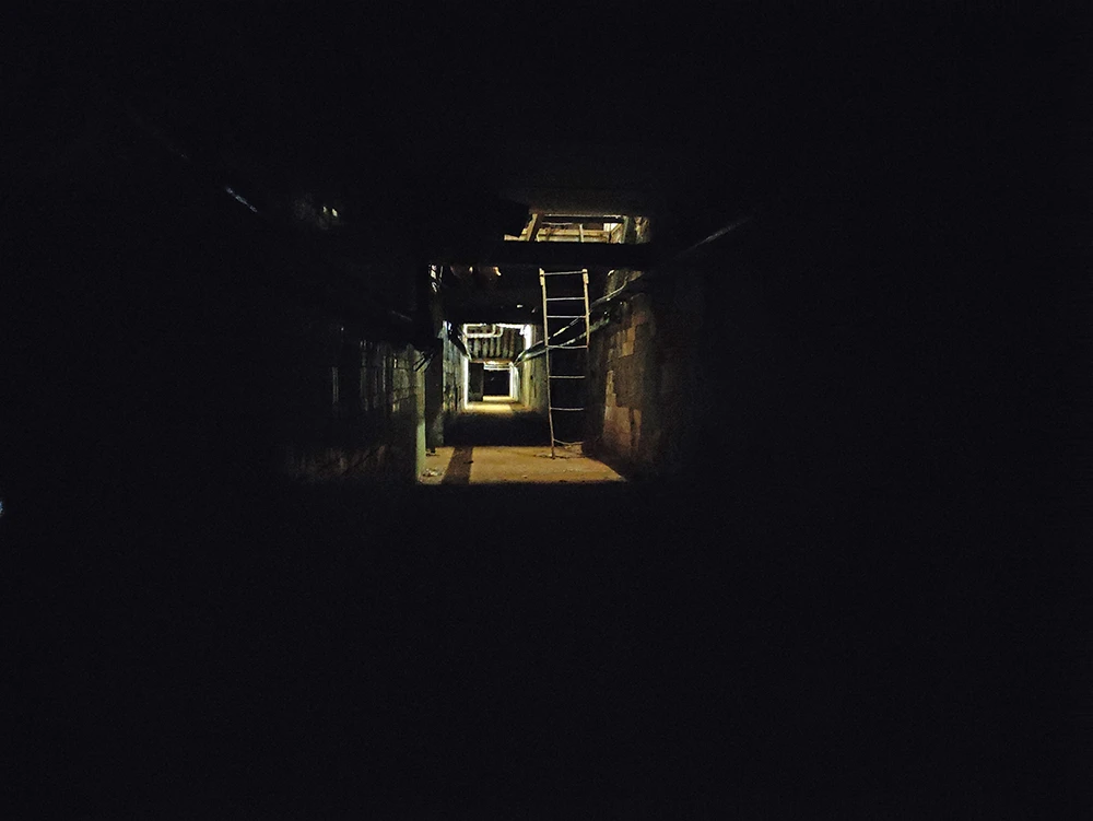
After walking about a hundred meters along the collector, we discovered an interesting feature. The height of the collector is about 2 meters, but suddenly we came across a section that was several meters higher (photo 11). This chamber was about 6 meters long and contained no equipment other than pipes. So why build such a chamber?
The answer is quite simple. For deep underground structures, installation shafts or chambers are created through which soil is lifted (if necessary) or building materials and equipment are lowered into the system for further installation. After completion of the work, this shaft/chamber is closed. When carrying out repair work or replacing pipes and equipment, this chamber can be opened from the surface and used for dismantling/installation.
8. Someone had already opened the boxes and scattered the gas masks. Photo taken from the tunnels through the barred doors
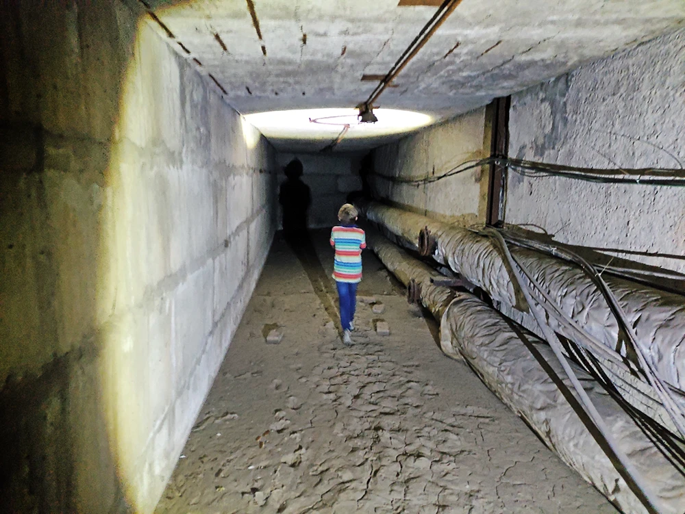
9. Passageway plumbing tunnel. Remnants of a huge air duct on the floor
10. The start of the pipe and cable collector looks promising. Of course, compared to the plumbing tunnel, it looks more interesting
11. Assembly chamber through which building materials and equipment were loaded into the collector. Photo by Andrey Woland
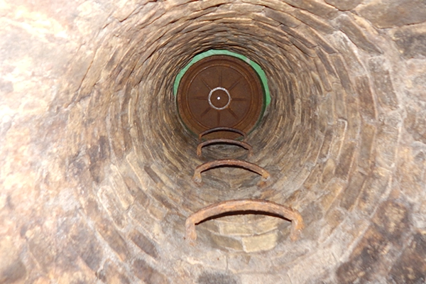
Moving along the collector, we paid attention to the wells (photo 12) that led from the ceiling to the surface, counting the number of well rings (standard height of a concrete ring is 890 mm), it became clear that there was approximately 5.5 meters of soil above us to the surface, i.e., the depth (floor level) of the TCC was approximately 7.5 meters. A pleasant bonus was the well-laid (by some perfectionist) electrical wiring in the pipes on the ceiling, which ran in semicircles around the wells, drawing special attention to them.
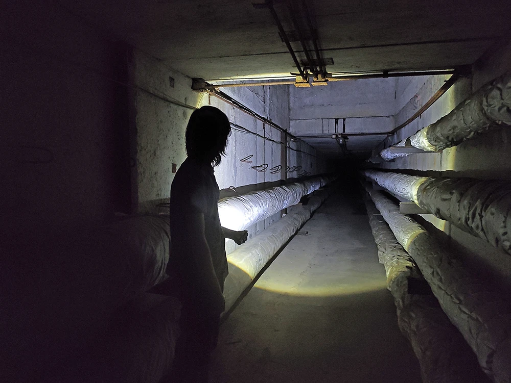
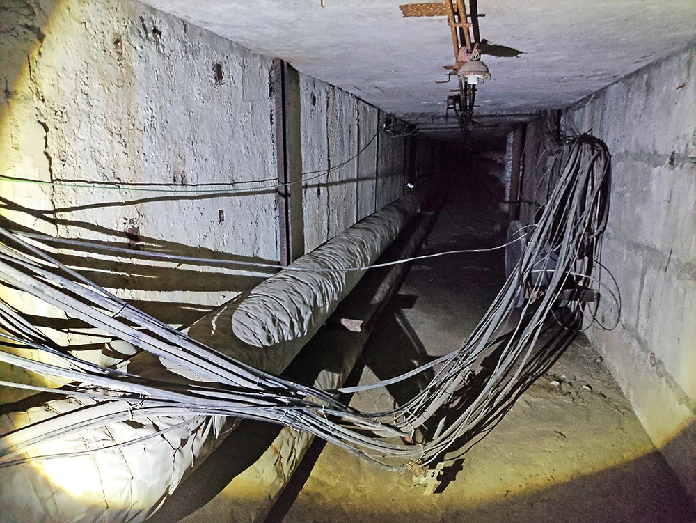
The pipe section of the manifold looked quite neat, but further on, a bundle of wires had been fed into the manifold, which made this tunnel look a bit chaotic. Since the manifold was not equipped with brackets for laying cables, there was no question of organizing the wires here. The cables either lay on the floor or on the pipes, or even crossed the passageway of the manifold, and we had to carefully crawl through these wires (photo 14). It was interesting to find a huge plastic spool of wire that the cable workers did not bring to the surface (photo 13).
12. We examine the wells and count the number of concrete rings to determine the depth of the collector installation
13. Cable installers left a huge reel in the manifold, from which they laid wires
14. A slightly dangerous section that we had to cross without getting caught on the wires
15. Water brought mud here, but it has dried up in this part of the collector, so we are moving on
Upon examining the TCC, it became clear that it runs parallel to the plumbing tunnel (we planned to go in the opposite direction along it), and sometimes they have connecting portals through which you can get from one tunnel to another and to additional staircases leading to the surface. But in the plumbing tunnel, there was some kind of plastic water pipe, which had probably recently burst, causing water to flow into the TCC and wash away the dirt (photo 15), which contained footprints of plumbers and large dog paws (here it is appropriate to joke that they were probably werewolf plumbers).
Ventilation wells were installed in the far reaches of the collector, which were closer to the surface (the depth here was less because the terrain sloped downward), through which we could hear people’s voices and the sound of cars, and through which a lot of human waste also entered (plastic and beer bottles, candy wrappers, bags, cigarette butts, etc. — everything that people were too lazy to take to the trash can).
The collector of this system was not straight; it had a (conditionally) zigzag trajectory and turned several times to the right and left (probably bypassing buildings on the surface) – this is more interesting than walking through a continuous straight tunnel. After walking about 350 meters, we reached the end of the collector. This was the lowest point of the system, because all the water that entered the system flowed here and drained through an opening in the floor into the city storm sewer system.
There was also a passageway to the plumbing manifold and one of the exits to the surface. The surface was very close here, because our phones had mobile internet reception and we could hear cars driving nearby. There was also an opening (covered with some kind of wooden shield) that led to the basements of the existing building (photo 17). Since we are not “intruders” and do not need any extra problems (there was a risk of encountering security guards or triggering an alarm), and since we were only interested in the underground system, we did not go into the basements of the building.
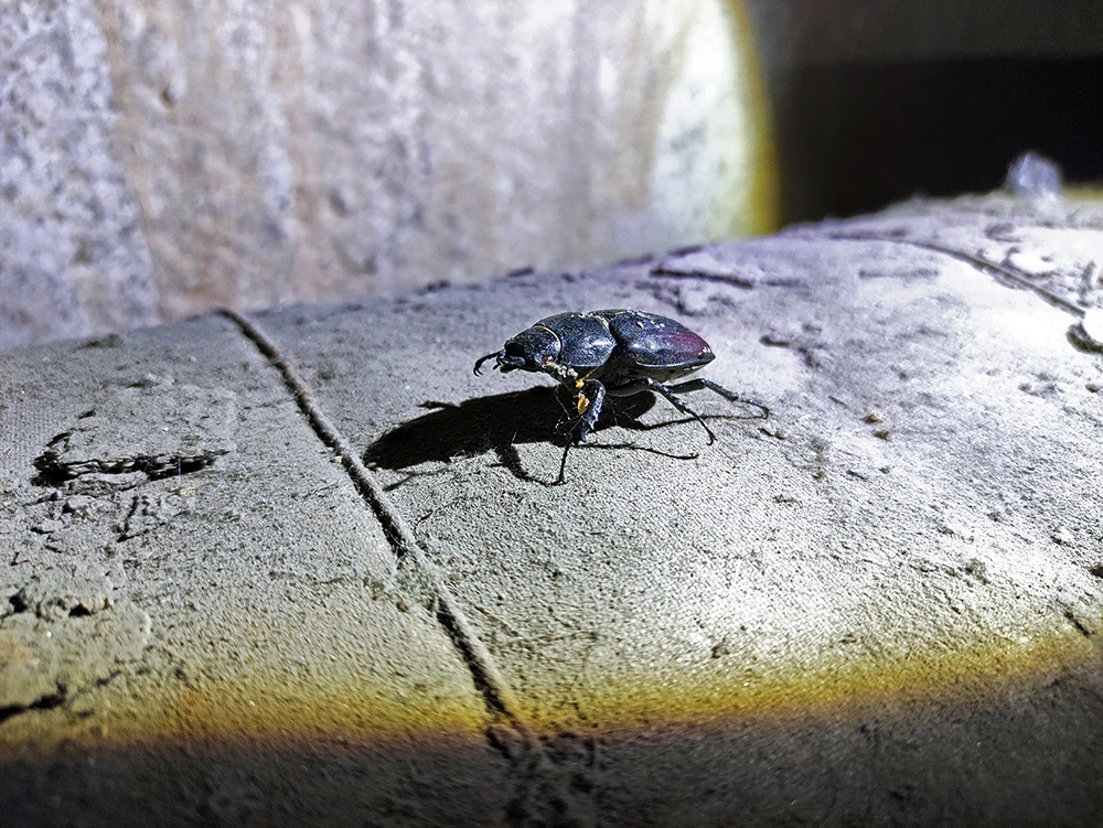
16. A beetle (probably a female stag beetle) that found refuge in the system and immediately ended its short life
17. Through an opening in the manifold, it was possible to enter the basements of existing buildings, but it was dangerous to go there
18. Such technological lamps were supposed to signal the presence of a technological (or emergency) exit from the system
19. Remnants of the air duct (placed a lamp there) in the plumbing tunnel
We wanted to return to the pumping station workshop via the plumbing tunnel, but part of it was still covered in wet mud after flooding (there had recently been a water pipe burst), so we had to walk part of the way back through the TCC again, to the nearest passage between the tunnels. The transition openings led to stair blocks of technological exits from the system (which are closed from the outside and now it is impossible to exit or enter through them), which should have been indicated by information lights – we found one of them on the floor (photo 18).
After making sure that the tunnel was dry further on, we moved along it. Its walls were tiled, and at one time a large air duct (photo 19) ran through it, carrying cooled air from the cooling and ventilation center to the buildings in operation. Later, we returned to the place where both tunnels began and where the boxes with gas masks were stored.
At the same level was a technological niche that overlooked the pump room located one floor below. Part of the niche was used as a utility area, where old boxes for clothes and some other pieces of furniture were stored. Andrei Voland examined them and found overalls (work clothes), empty liquor bottles, and faceted glasses—oddly enough, this is the most common find in utility rooms.
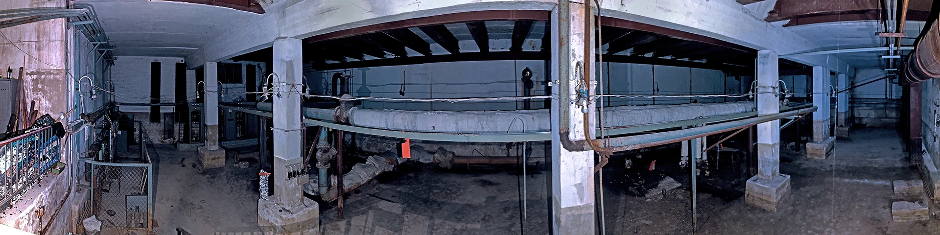
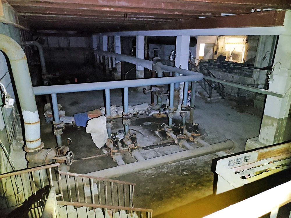
Looking around the underground pumping station workshop from this level, it seemed too big to us (for an underground structure), because the only structures I had seen that were bigger were subway stations. Later, after checking the city’s engineering diagram, I calculated the dimensions of this workshop: 20 meters wide, 50 meters long, and 7 meters high.
20. Even this panorama does not convey the actual space of the underground pumping station that was located here
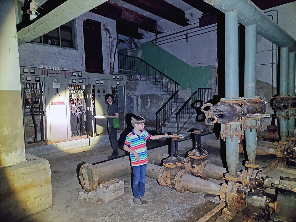
First look from the niche level: on the right was the power unit, and in the far corner were stairs leading to the second level to some rooms, in the middle were the remains of some equipment, and on the right were those large air ducts that we saw in the plumbing tunnel. We will examine everything in more detail after descending into this underground workshop.
Near the staircase, we smelled a strong odor of fuel and lubricants. Looking under the staircase, we found a storage area with empty barrels and oil cans. Naturally, some of them were damaged, and the liquids inside were spreading across the floor in huge oil stains.
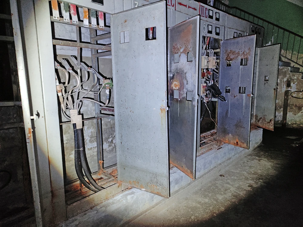
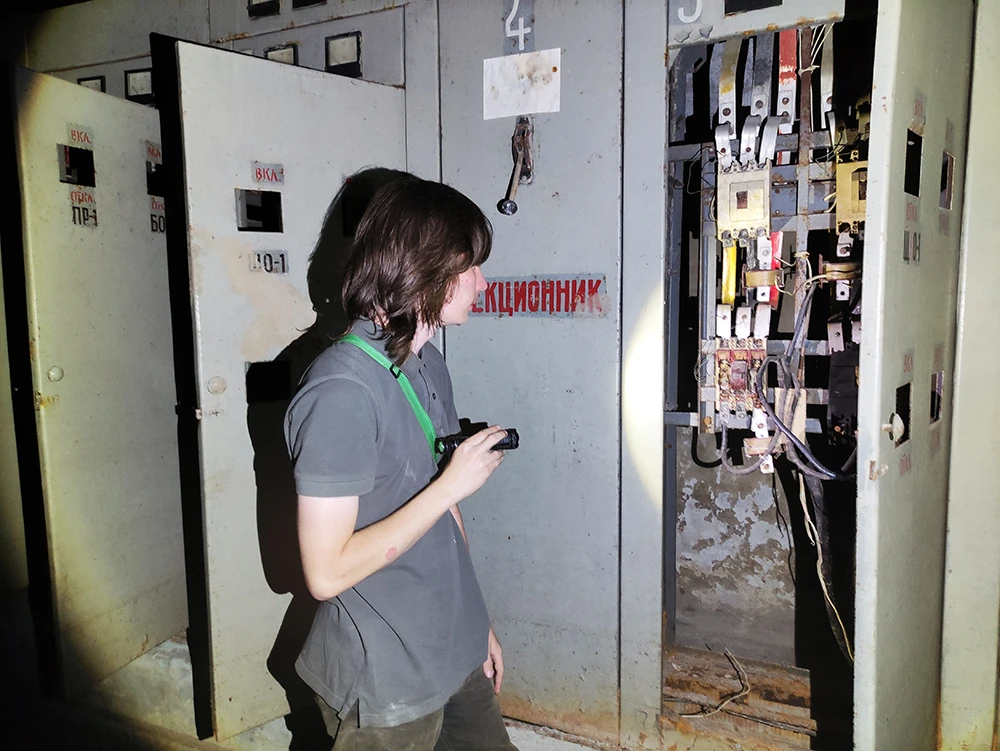
Near the staircase along the walls were two power units – here stood electrical cabinets, which had already been opened and whose equipment had already been partially dismantled. One of the electrical equipment units was fenced off by a 1.5-meter mesh fence – presumably, this was where the high-voltage part was located. This was later confirmed by Andrei, who examined the remains of the equipment and found insulating caps from high-voltage disconnectors (which prevent the electric arc from escaping beyond the cap).
Since I don’t know much about electricity, I can’t give any details. The only thing I can add is that there were two power units here, one responsible for the pumping equipment and the other for the ventilation equipment.
My opinion about the functional purpose of the two electrical installations was confirmed by the fact that there were air duct outlets above one of them, and there was a large ventilation chamber in the adjacent room. The ventilation chamber was flooded, so we were unable to examine it in detail. In the light of the flashlight, we could see the “snails” of the ventilation units. But in the water, besides the remains of equipment, there was something alive—and this is no joke. At first, we thought there were rats here, but later we found a small number of amphibians in this system, namely toads.
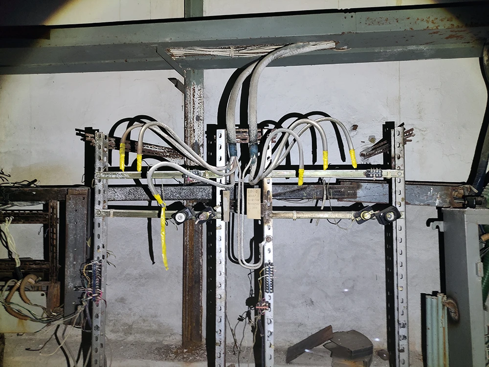
21. Electrical cabinets responsible for powering the pumping station and ventilation equipment
22. Andrei Voland examines the remains of electrical fittings in a sectional cabinet
23. The electrical cabinets are no longer complete; someone has already “help themselves” here
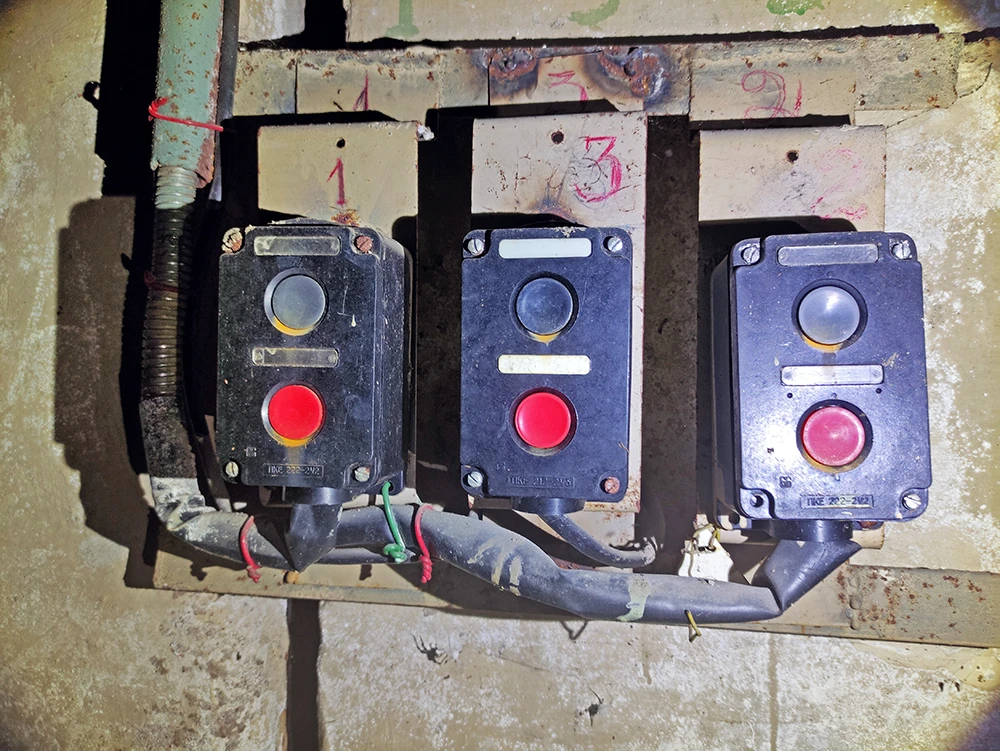
24. Double-action push-button control station (off/on)
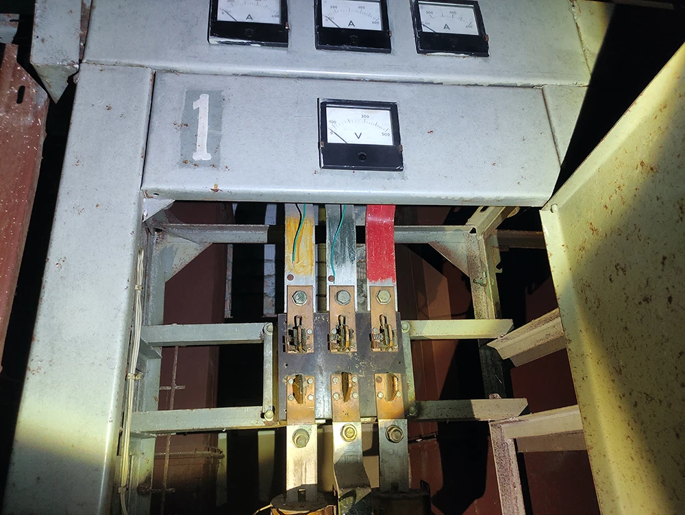
25. The busbar remains, but the hardware to which the current was supplied is no longer there
26. Entrance to the ventilation chamber (below) and stairs to the second level leading to the service rooms
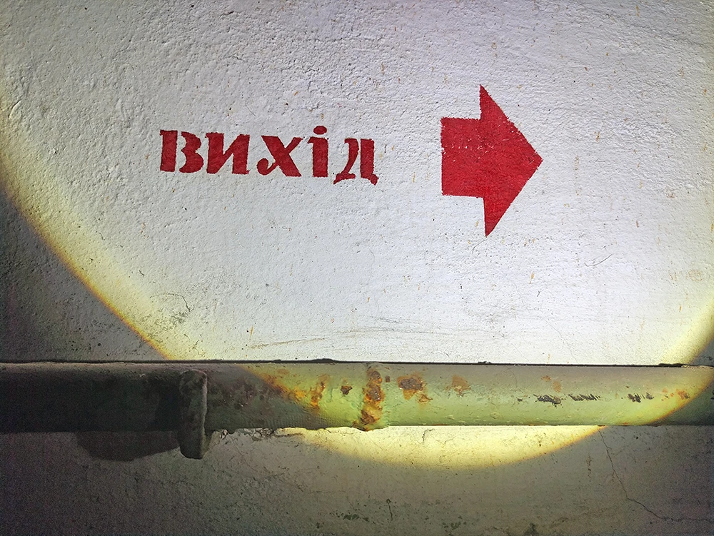
27. The sign “tells” staff on the 2nd floor where to evacuate
28. The corridor on the right led to the emergency exit and public restroom
Above the ventilation chamber was a second level with rooms, one of which had a viewing window facing the pump room—this was probably a control room with workstations for the pump room and ventilation chamber operators. In the corner of the shop there was a staircase leading to the second level (photo 26) – we headed there. The control room was closed – unfortunately, breaking locks or doors is not our policy. Two corridors led from the staircase. A sign on the wall pointed to the right with the word “Exit” (photo 27), so I went down that corridor (photo 28), while Andrei and Mark stayed near the control room. This passage led me to a vestibule, from which a staircase led to the surface. I could smell fresh air, see light, and hear voices from the surface, but I didn’t know where exactly I would end up, so I didn’t rush. I looked around, saw two more doors, pulled them, and they opened. The rooms behind the door were tiled, and there was dried mud on the floor—the room had once been flooded… and here was the reason—a broken sewer pipe, so this substance was not mud at all (sorry for the details). I found a number of plumbing fixtures here, so there is no doubt that these rooms were once an underground public toilet that served a specific facility, but now its clean rooms and stairwells were being used as a warehouse.
Here, as usual, there were two toilet blocks—one for men and one for women—and each had a separate staircase to the surface, but the exits were closed with barred doors. There was nothing else of interest here, so I returned to Andrei and Mark.
The guys had already checked out the corridor leading to the left—it led to the pump station operators’ utility rooms (staff room, bathroom, shower room, storage room).
After inspecting all the adjacent rooms, passageways, and collectors, we went to explore the pumping station workshop.
29. View of the pumping station workshop from the control room level
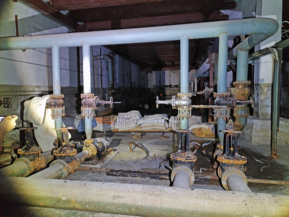
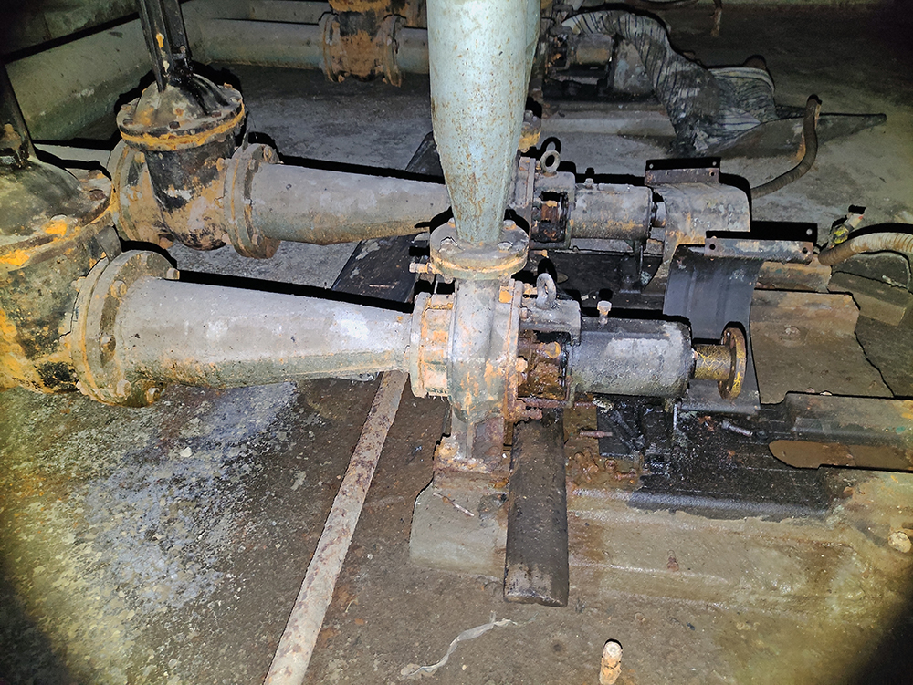
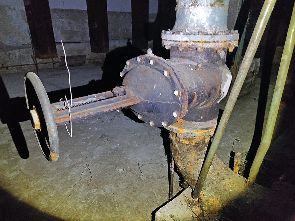
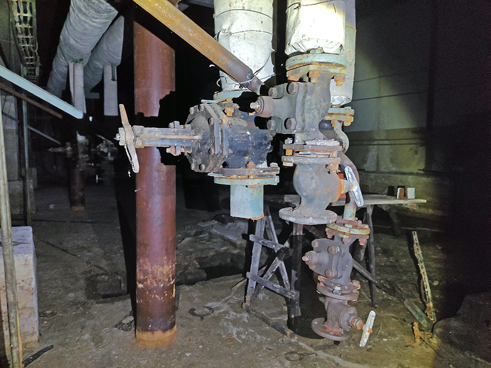
30. Closed water supply system with a station for four pumps
31. These are probably dynamic centrifugal pumps, but the motors that drove them are no longer there
32. While Andrei examines the electrical components, Mark takes an interest in the water supply system
Among the more or less preserved equipment here was a closed water supply system with a station for four centered pumps (photos 30-31). The pumps themselves are small, but they must have been rotated by powerful electric motors, which are no longer there, so it is not immediately clear that there is any equipment left here. Mark was very interested in this station—it reminded him of an animated screensaver in the old Windows (Pipes or Pipeline 3D screensaver)—he was very happy about this, saying that “he finally saw it in the real world”.
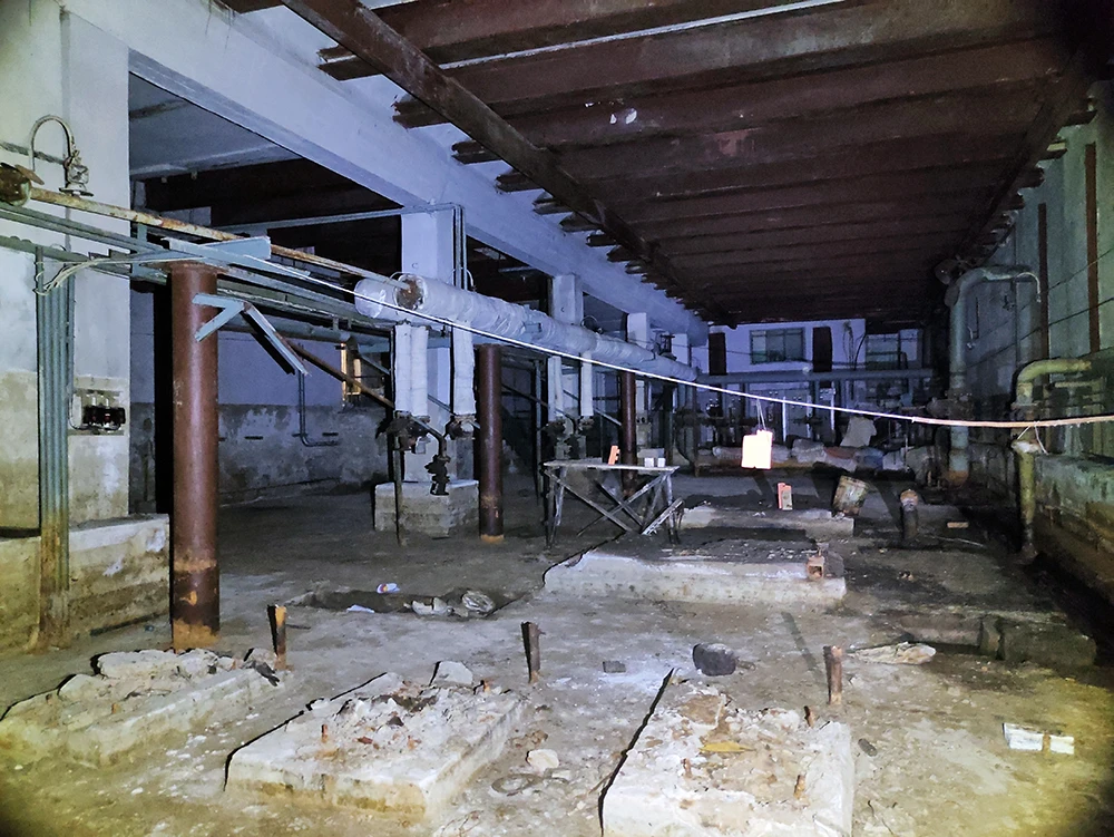
In the far part of the workshop, there was no equipment left (photo 32) – everything had been dismantled, leaving only the foundations for the units and pits (either for collecting condensate or oil). Some pipes still lead to equipment that no longer exists (photo 33-34). A channel for collecting and pumping water ran along one of the walls.
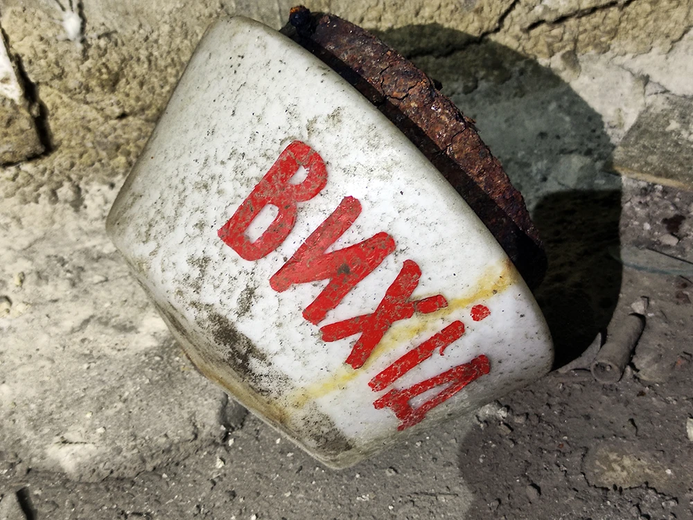
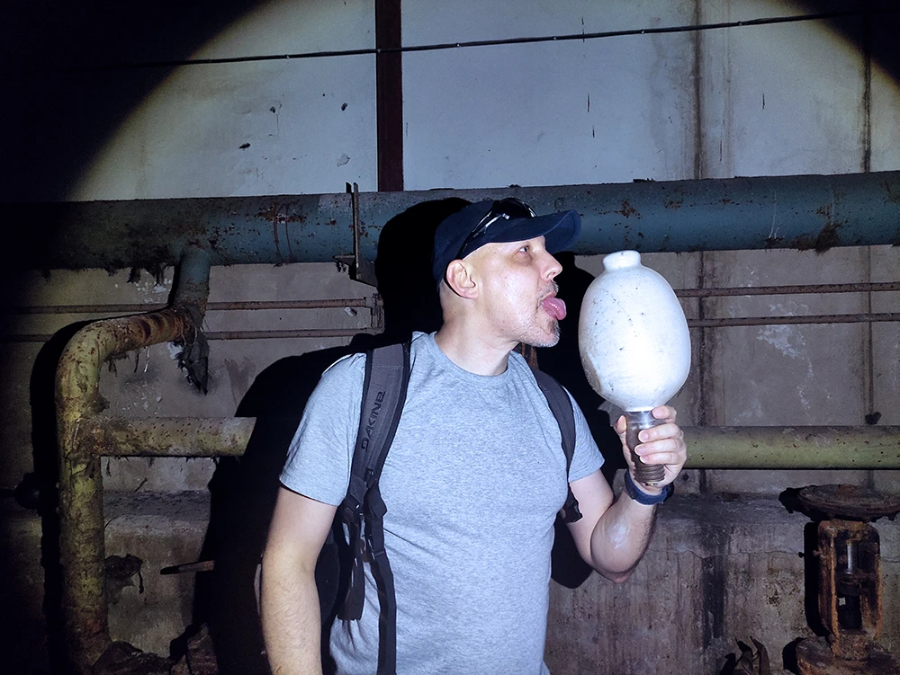
We found a huge DRL-1000 mercury lamp here—without a doubt, it’s the largest lamp I’ve ever held in my hands. We carefully examined our find (photo 35). It reminded me (depending on how you hold it) of either a glass jug of milk or a giant ice cream cone, so I couldn’t resist taking a funny photo with the “giant ice cream” (photo 36).
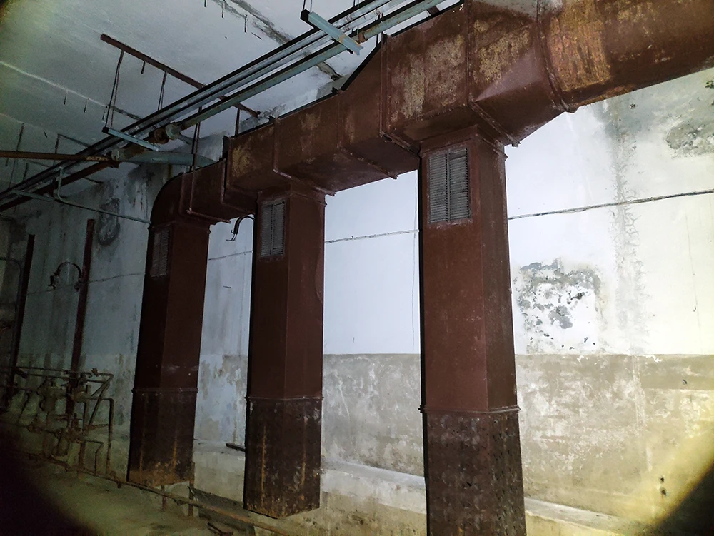
Only one question remained to be answered: how did this system function as an air conditioner? To understand this, I had to examine everything. The last piece of the puzzle was the air intake hoses (photo 37). Now I have a rough idea of how this system worked.
I’ll try to explain roughly:
The closed water supply system circulated through a fountain on the surface, where the water was cooled, then returned to the underground system and, probably through some heaters or radiators, cooled the air temperature in the system.
The ventilation system drew fresh air from the surface, released it into the system (there were several large air ducts above the electrical equipment that supplied air from the surface), creating excess pressure and forcing it through cooled or heated radiators (depending on the season / remember, there is a boiler room in the system that could be responsible for heating water). The air circulated in the underground system through the appropriate equipment in the pump room and heat exchange chambers, acquiring the required temperature.
Through intake ducts (photo 37), air entered a huge air duct, through which it was transported via a sanitary tunnel to buildings, where it entered the local ventilation and air conditioning system of the building.
32. The far end of the pumping station workshop is empty – the equipment has been dismantled
33. Pipe scraps and shut-off valves
34. Here you can see that not only the equipment but also the pipes were cut off
35. DRL-1000 mercury lamp – impressive size
36. Don't do that—I was just messing around for a funny photo
37. Air intake hoses for the air conditioning system
Our time in this interesting underground complex was limited, so we don’t have many photos. It’s difficult to convey what we saw in this article, and photos cannot convey the scale of this system, so I recommend watching the videos we took (video in Ukrainian):
Underground HVAC – penetrated the engineering system
Part 1
Part 2
Finally, for those who are interested in our activities, here are the links to our online resources.