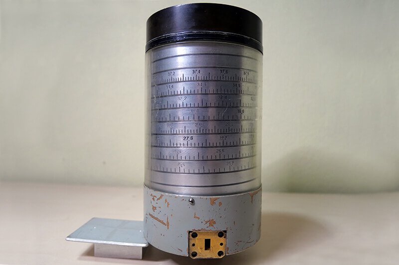
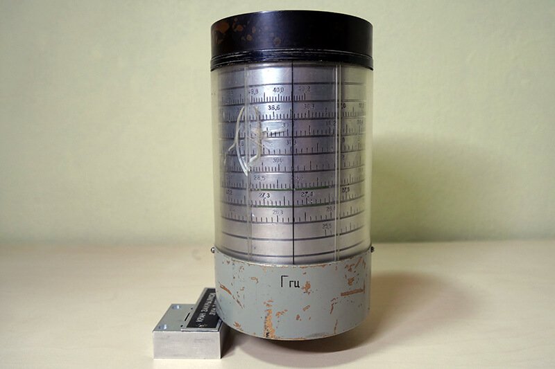
A Soviet microwave frequency metre manufactured by the ‘Saturn’ factory in Kyiv, operating at 25.5–40.2 GHz
This cylinder was a gift from one of the employees of Saturn Private Joint-Stock Company when another room at the research institute was converted into an office to be leased to the company “Bought—Resold.”
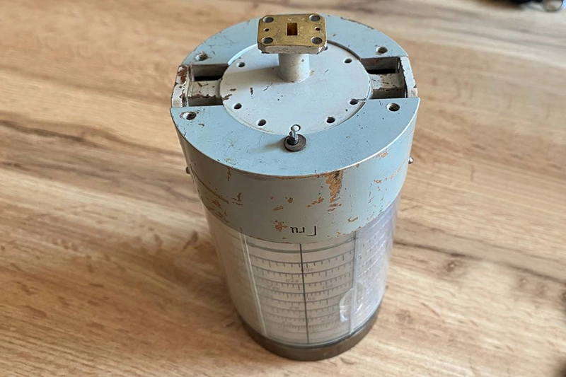
This rather heavy component—whose purpose was initially unclear, featuring holes and a “GHz” scale—turned out to be a microwave-range waveguide frequency meter: a mechanical measuring instrument designed to determine the frequency of a microwave signal in a waveguide path. It was no coincidence that this device ended up at the facility; rather, it was entirely logical, since the “Saturn” Research Institute had participated in the development of deep-space communication systems for the “Venera-15,” “Venera-16,” and “Vega,” as well as satellite television equipment, 59–64 GHz inter-satellite communication systems, 22–118 GHz radiometric complexes, and 94 GHz radar equipment.
Waveguide Design
At the bottom of the frequency meter are two identical rectangular ports; they are positioned opposite each other and connected internally by a straight through-channel. This constitutes the device’s main waveguide path.
At low frequencies, an electrical signal can be transmitted via conventional conductors or coaxial cable. However, in the microwave range—especially at tens of gigahertz—metal waveguides are widely used.
Essentially, this is a hollow metal channel with a precisely defined cross-section, within which an electromagnetic wave propagates.
The internal dimensions of the rectangular channel in this frequency meter are approximately 7 mm by 3 mm, as measured with a ruler rather than a vernier caliper. This corresponds almost exactly to the standard WR-28 waveguide, which has an internal cross-section of 7.112 × 3.556 mm. Its standard operating range is 26.5–40 GHz.
How It Works
The device operates on the principle of electromagnetic resonance. Two rectangular side ports form a through-path: the microwave signal enters through one port, passes through the device, and exits through the other. Separate from this path is a third, perpendicular channel. On the outside, it also begins with a rectangular opening, but its geometry then changes and transitions into a narrowed section.
The principle of operation of resonant microwave meters is that the resonator is tuned to the signal frequency. When its natural resonant frequency matches the frequency of the electromagnetic wave in the waveguide, the way energy passes through the path changes.
In simplified terms, the operation of this device can be represented as follows: microwave signal → waveguide input → through-path → waveguide output, with a tunable resonator electromagnetically coupled to the main path.
The operator rotates the frequency meter’s cylinder. The mechanical mechanism changes the parameters of the resonant system and, along with them, its resonance frequency. When the resonator’s tuning matches the frequency of the signal under test, this can be detected by a change in the signal level in the path. After that, the frequency value is simply read off the scale.